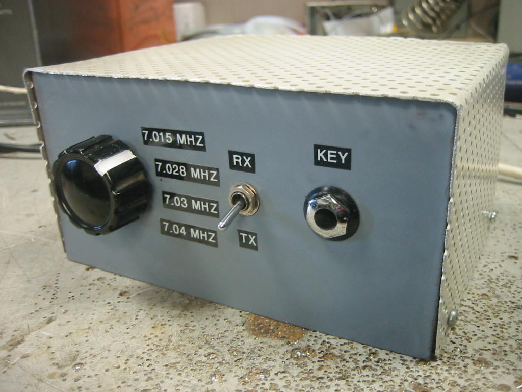
The G-QRP Club sells a good range of 40M CW xtals at a very reasonable price. Here is a very cheap and easy to build transmitter using these xtals. Power output is approximately 6 Watts for a supply voltage of 13.8 VDC ( if you experiment with the Pi output values and FET bias then over 10 Watts can be had, but a large heat sink will be required for the FET ). Construction is made easy by using a pad cutting tool for the circuit board - this tool is also available from the G-QRP Club. Easy to obtain components are used throughout the design.
The circuit consists of a colpits xtal oscillator TR1 followed by a diode switch D1, D2 , a driver TR2 and PA stage TR3. A zener diode ZD1 stabilises the DC supply to TR1 stage, this oscillator runs continuously to avoid any chirp etc. The oscillator output is keyed by a diode switch consisting of D1, D2 and their associated components. Capacitor C1 provides some envelope shaping of the keyed waveform, it is isolated from RF by L1. On key down C1 gradually charges up towards the supply rail via D4 and R1, thus D1 and D2 become forward biased allowing the oscillator signal to pass to TR2 without a steep rising edge of the waveform. On key up, C1 discharged via R1, R2 the time constant of which eliminates a sharp falling edge of the waveform. Tr2 is biased to class B via D3. It's collector load consists of L2, VC1, a parallel resonant tuned circuit. A low impedance tap on L2 feeds TR3 gate. The gate is heavily swamped by low impedance bias network and L2 tap, this is to overcome the 150Pf or so of gate capacitance that would otherwise be difficult to drive. TR3 is biased for a standing current of 200 - 250mA by VR1. The drain load for TR3 is a Pi network, the 80pF ( approx ) of output capacitance exhibited by TR3 is taken into account for the network component values. A low pass filter ( L5 and L6 ) follows the Pi network. A two pole two way switch is used for antenna switching, DC supply to the transmitter and also a mute voltage for a RX IF. A matching RX is currently under construction for use with this TX. As mentioned earlier, it is possible to obtain 10 Watts output simply by changing the 880pF capacitor in the Pi network to a 1200pF and increasing TR3 standing current to 800mA. However, I do not recommend this unless you fit a large heat sink to TR3 as it does run very hot at this power level. The receiving station is unlikely to hear any difference between 6 and 10 Watts Tx power, I run mine at 6 Watts for a total current drain of 750 mA, if you require 5 Watts exactly, reduce Tr3 bias voltage accordingly. Alignment of the finished transmitter is simple, with no drive set the standing current of TR3 to 200 - 250 mA. Apply drive and adjust VC1 for maximum output power. Adjust the xtal trimmers for exact xtal frequencies, these trimmers were only included in case several of these transmitters are built for use in a net and all produce the same TX frequency. You may note an extra transistor on the circuit board, this is used as contact closure to ground key switch so my electronic keyer can be used with this set. The front and back of the case is made from some copper clad board, the circuit board forms the bottom of the case. The lid of the case is made from a perforated aluminium ceiling tile.
Barry Zarucki M0DGQ
HOME